An Electronic Music Project
The Composition of Pulse Music III
by John McGuire
Note: This page contains 27 graphics from the original publication and will take some time to load them all.
I
The first experiments made in connection with the composition of Pulse Music III were attempts to reproduce an aural image which had preoccupied me for some time, an image which did not seem in any way related to acoustical instruments or voices. It involved a certain kind of motion, rather than a particular sound. The problem was to find a way of reproducing this imagined motion, and to find those sounds which would best embody it. A commission to realize an electronie piece in the Studio für Elektronische Musik at the West German Radio, Cologne, in 1978, provided an opportunity to pursue the problem.1
The image could be described as follows:
- A sound issues from a distant point on the left, approaches and passes the listener, and vanishes at an equidistant point on the right, forming a symmetrical wave.
- A series of overlapping symmetrical waves forms a continuous, uninterrupted stream, as though the issuance point were a fountain, the vanishing point a bottomless hole.
- Several streams pass by simultaneously at different speeds; the speeds keep changing.
Having no idea whether or not such an image could be realized, I tried at first to develop a sounding model of its first two components, overlapping symmetrical waves forming an uninterrupted stream, that is, a spatial motion with no apparent beginning or end. I recorded two series of pulses, each series with a different pitch. The two series alternate on each pulse: 121212...etc. Series 1 was dynamically regulated so as to move from left to right, starting barely audibly on the left, increasing in volume to a peak at the center, then decreasing again to barely audible on the right, whereupon the movement is repeated.2 Series 2 makes an identical journey, starting from the far left just as series 1 reaches the center. Thus the two pulse series were interlocked and their regulating envelopes overlapped so as to form a continuous, looping motion in space. (The forms of these envelopes have been simplified in the examples that follow. A more detailed description of one envelope is included in the technical notes at the end of this article.)
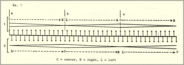
Four aspects of this example were essential to the subsequent forming of the piece.
- pulse frequency
The pulse frequency was defined as the combined speed of the two alternating pulse streams.
1 e.g. 4 Hz (Hz = Hertz: pulses per second)
2 e.g. 4 Hz
pulse frequency = 4+4 = 8 Hz
- envelope frequency
The envelope frequency was defined by the duration of one increase or decrease in volume, i.e. one of the three parts a, b or c of example 1. The term "frequency" is used here because these durations are periodically repeated in a way structurally analogous to the pulse repetitions (see below).
1 
2  = 1 envelope duration (= e.g. 3.125" = 0.32 Hz)
- the absolute number of pulses
Each envelope contains an odd number of pulses (25 pulses in example 1). This allows the placement of a single pulse at the peak of the envelope, framed by one pulse at the extreme left and right.
- pitch and interval
It was found that series of clear, staccato pitches, placed a fourth or fifth apart, were easiest to distinguish and locate in space. The sounds consist of harmonically tuned mixtures of sine tones.
Example 1 seemed to be a reasonably satisfactory realization of the first and second characteristics of the motion outlined above. The third part of the description required the development of more complex structures, particularly since changes in the velocity of the streams would have been gratuitous unless the changes could be felt to be a consequence of the way in which the streams were combined. This meant that simultaneities and successions of streams would have to be so closely interrelated as to be interchangeable, that is, generated from a single source. Though this was ultimately the case, it will be clearer at first to describe the techinques used to form the simultaneities and successions separately.
simultaneity
To obtain some experience in setting up combined structures I again worked out a sounding model. The number of streams to be combined in this model was arbitrarily set at two. I used a ratio for the combination of two pulse velocities which was consistent with the stipulation that the envelopes contain an odd number of pulses, that is, a ratio consisting of odd numbers. The model was based on the ratio 3:5.
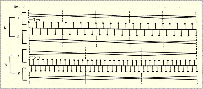
In A the slower pulse speed is combined with the faster envelope speed; in B the faster pulse speed is combined with the slower envelope speed. This type of reversal resulted from the procedure used in combining successions of structures (see example 14). All envelopes in this and the following examples refer to movement in space as well as to changes in volume, as in example 1; these movements are of two kinds: left to right and front to rear. The left-right motions are confined to layer II and the front-rear motions to layers I and III (see example 6 and the technical notes).
The model depicted in example 2, even with the simplest of sounds and pitch relationships, was already so difficult to grasp that I felt some form of clarification to be necessary if, as planned, it was to serve as the model for an entire piece. Further experimentation showed that period combinations like this could be considerably clarified if such virtual frequencies as result from the combination are made explicit. These are the "product" and "coincidence" frequencies in example 3. The total set of velocities arrived at in this way will be henceforth referred to as a constellation. The frequency components of such a constellation have different, reciprocally supportive, functions.
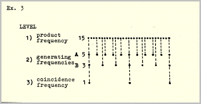
- Level 1 is the product of the relationship 3:5 (15), whose frequency is equal to the shortest interval between pulses on level 2 and thus marks each stage in the crossing of the two pulse series A and B.
- Level 2 A and B have the frequency relationship 3:5 and thus generate levels 1 and 3.
- Level 3 defines the limits between which all the phase relationships implicit in the ratio 3:5 are exhausted by marking the pulse coincidences of A and B.
Application of the alternating pulse structure of example 1 to all three levels of example 3 results in the following constellation:
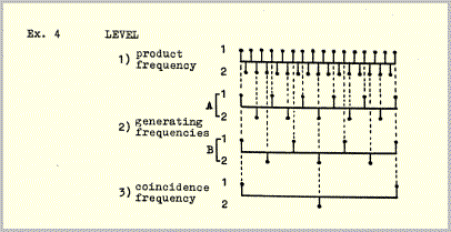
If each level is provided with an alternating envelope pattern like that in example 1, the result is analogous:
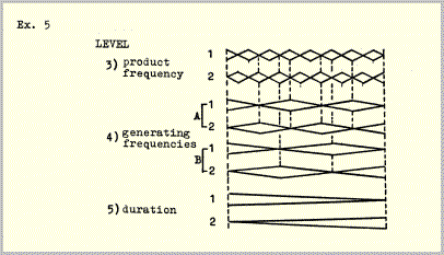
The constellation can be completed by combining examples 4 and 5:
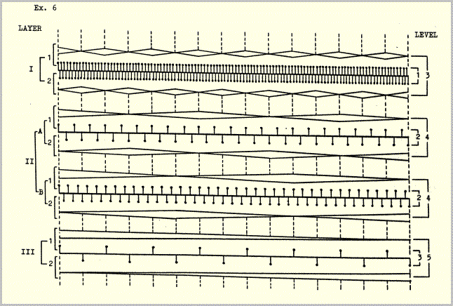
The four pulse frequencies and four envelope frequencies in example 6 add up to a total of seven frequencies; the envelope frequency of layer I (levels 1+3) is identical to the pulse frequency of layer III (levels 3+5). The following example illustrates the frequency hierarchy of example 6 (this constellatlon can be found, with somewhat different time values, in sections 3, 11 and 19 of example 14).
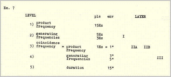
Pulse frequencies (levels 1, 2, 3) are shown in Hz (pulses per second); durations of envelopes (levels 3, 4, 5) are shown in seconds.
succession
Successively occurring constellations are linked by common frequencies. This linkage is again based on binary alternation. Each constellation contains two pairs of generating frequencies, one pair at level 2 (pulses), the other at level 4 (envelopes). The completion of one phase cycle (example 6), i.e. the coincidence of envelope peaks at level 4, triggers a change in speed in one member of each pair, thus forming the next constellation. The following example is a schematic depiction of the way in which successive constellations are so linked.

Sections 1-2, 3-4 etc. are linked by pulse frequencies B and by envelope frequencies A; sections 2-3, 4-5 etc. are linked by pulse frequencies A and by envelope frequencies B. Product and coincidence frequencies (levels 1, 3 and 5), because they are generated by A:B, change in every constellation.
The frequency changes are determined by the same ratios that determine the internal frequency structures and durations of the constellations (the duration of a constellation is simply its lowest "frequency", i.e. the only time value that does not repeat). The envelope peak coincidences which trigger the changes occur alternately on the ones and twos (hatched envelopes, example 9).
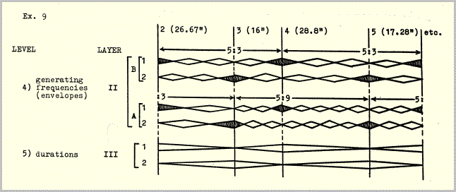
The condition necessary to bring about this alternate triggering is that all of the constellations be formed from odd numbers of envelopes (such as 3, 5, 9, 15). Since each envelope contains an odd number of pulses (example 1) the stipulation could be made that only ratios comprised of odd numbers be used in formulating the time structure. Therefore if an entire constellation is repeated, it would have to te stated an odd numter of times, otherwise the pattern of alternating triggering would be destroyed. In example 10 the same constellation occurs three times ('b' is not a repetition, but a retrograde, of 'a'). In order to postpone for as long as possible the decision as to whether or not a constellation would be repeated, both versions 'a' and 'b' were produced for each of the 24 eonstellations, though in many eases only version 'a' was used.
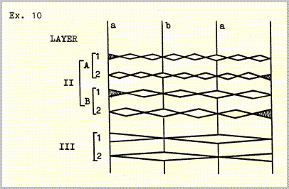
Assuming that adjacent constellations are to be linked by alternating common frequencies according to the scheme in example 8, two things are needed to construct a succession of constellations: 1) a chain of interlocking odd-number ratios, and 2) vertical ramification of the ratios so as to generate the five frequency levels.
In the 1950s Stockhausen demonstrated that chains of interlocking frequency ratios can be generated by certain kinds of frequency series, that such ratios are equally applicable to the domains of pitch and duration, and that (as in examples 11 and 12) duration proportions can therefore be conveniently represented by pitches.3 What is needed in this case is a set of intervals describable by odd-numbered ratios. Three possibilities were chosen:
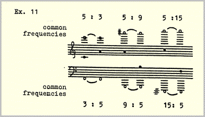
The lower ratios indicate the positions of the two successive frequencies ( ) with respect to a common harmonic fundamental (
 ); the upper ratios indicate the positions with respect to a common subharmonic fundamental (
 ). The two interpretations - harmonic and subharmonic - are in this ease of equal importance.
The ratios are automatically interlocked when a series of frequencies is formed consisting exclusively of these intervals.
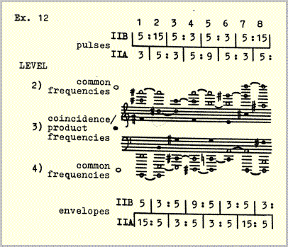
The three frequency levels correspond to levels 2, 3 and 4 in example 14. In order to represent all 5 levels and avoid using too many ledger lines, it was necessary at this point to switch to graphic notation. Between each of the heavy lines in example 14 there are 12 light lines representing divisions of the interval 1:2 (octave) into 12 equal steps, for example:
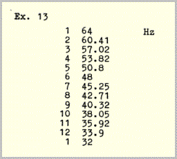
Even though the relationships between the frequencies in this scale are of course "tempered" - there are, for example, no exact ratios of 3:5 or of 5:9 to be found - these discrepancies apply only to successively occurring frequencies, not to simultaneities, where the ratios, all arrived at by subharmonic division, are exact. In the case of successive frequencies, most of which are below the pitch threshhold, the discrepancies are much too slight to be heard.
The procedure used in the construction of the five frequency levels was as follows:
- level 1: Using the above scale, a series of 24 different fast frequencies (see Technical Notes - trigger pulses) was produced.
- level 2: The interval ratios of this series were used to generate a chain of common or connecting frequencies; each pair of adjacent frequencies in level 1 is joined by one common frequency.
- level 3: The interval ratios were reversed in order to generate a second 24-part series which is necessarily identical to the series of level 1, though shifted by one part.
- level 4: The procedure of level 2 was repeated, thereby generating another series of common frequencies.
- level 5: The procedure of level 3 was repeated, thereby generating a third 24-part frequency series, which is again necessarily identical to the series of level 1 - here shifted by an additional part.
The five levels were distributed among three sounding layers as follows:
| layer I | level 1 pulses
level 3 envelopes |
| layer IIA, B | level 2 pulses
level 4 envelopes |
| layer III | level 3 pulses
level 5 envelopes |
In this way the five levels determine the number of pulses per envelope and the number of envelopes per section for each of the 24 sections.
To further clarify the way in which the five levels were distributed among the three layers, it may be useful to detail the construction of one of the 24 sections - example 14, section 3 (see also example 6):
- layer I: The interval (i.e. the frequency ratio) between levels 1 and 3 is 1:15, therefore the envelopes in layer I each contain 15 pulses.
- layer IIA: The interval between the frequencies drawn in straight lines at levels 2 and 4 is 3x3=9, therefore the envelopes in layer IIA each contain 9 pulses.
- layer IIB: The interval between the frequencies drawn in wavy lines (
 ) at levels 2 and 4 is 5x5=25, therefore the envelopes in layer IIB each contain 25 pulses.
- layer III: The interval between levels 3 and 5 is 1:15, therefore the envelopes in layer III each contain 15 pulses.
Similarly the ratios drawn beneath the frequency series of levels 3, 4 and 5 show the number of envelopes per layer in each section. Again taking section 3 as an example, layer I has 15 envelopes, layer IIA 3 envelopes, layer IIB 5 envelopes, and layer III one envelope.
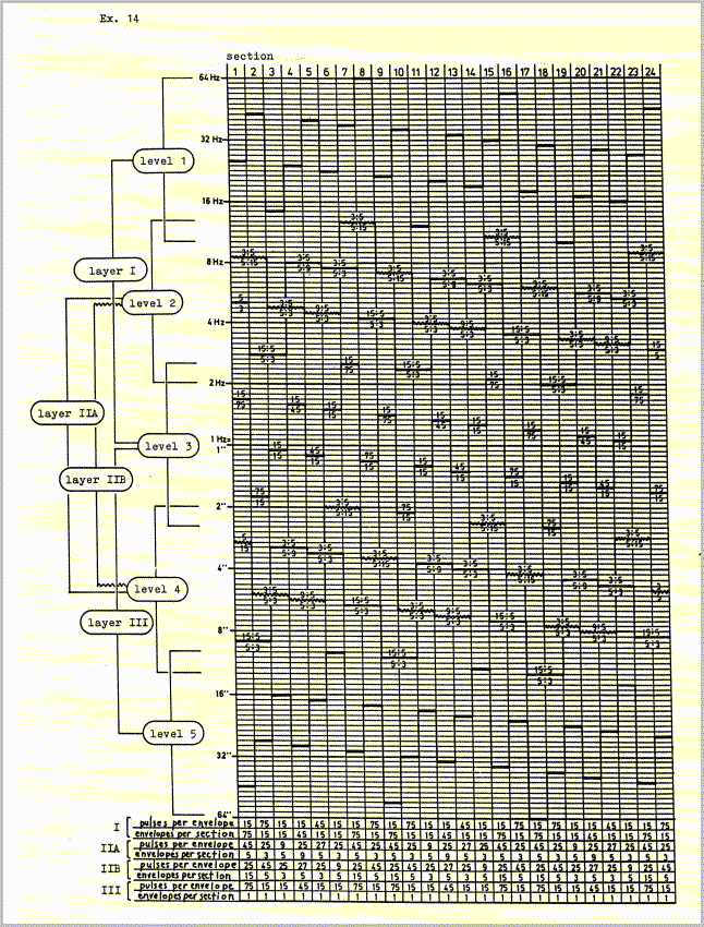
The plan illustrated in example 14 was intended to help generate the aural image described at the beginning of this article from a few basic structural units and formative processes suggested to me by the image. The structure which eventually resulted makes use of a very few velocity - (or, as I have usually called them) frequency proportions, which determine all vertical and horizontal temporal relationships. The high degree of symmetry which appears as an accompanying phenomenon in all of these illustrations is brought about by two closely related considerations. Firstly, any combination of periods of different length - assuming that the periods are repeated enough times to run through a complete phase (i.e. coincidence - divergence - convergence - coincidence) will generate an irreversible left-right, or earlier-later symmetry around a central axis. In this case complete phases form the basic temporal units, or modules; they are never interrupted, because of the second consideration: The image referred to above is simply a cyclical motion, a kind of aural kaleidoscope, and contains no implications of dramatic developments or of long-range directional movements. The introduction of elements of this kind would, I felt, have compromised the image which gave the original impulse to the composition. Consequently it seemed that whatever events were to take place would have to be derived exclusively from the original image, and would therefore have to be free of affective implications or associations. The function of symmetry in this case is obvious: if a motion is presented in combination with its exact mirror image, then associations such as the aforementioned will be neutralized by mutual cancellation of the two motions. (Temporal symmetries in music are sometimes thought to have their source in naive or fallacious analogies to spatial symmetry, but this ignores the function that such symmetries, at least under some circumstances, can have, namely the neutralization of motion).
In developing the harmonic structure I encountered many problems analogous to those described above because it was of course imperative that the sounds which were to be "carried" by the pulses and envelopes concretize and clarify the temporal relations.
II
Each of the layers I, IIAB and III is comprised of mixtures of sine tones. The mixtures consist of fundamentals and selected overtones (principally 2,3,4,8, 9,16,18) produced individually on different oscillators which were tuned as "purely" as possible, though in the case of denser mixtures the instability of the oscillators made a certain amount of beating inevitable. Henceforth these mixtures will be referred to simply as "pitches". As notated in the examples below, each pitch refers to the fundamental of a mixture of sine tones unless otherwise indicated.
The pitches were organized by an harmonic plan whose function was to consolidate the disparate frequency components of the time structure so as to assist the emergence of certain resultant phenomena (see below, part III). The source of this harmonic plan was the application of the pattern of binary alternation of example 8 to a basic set of pitches such that half of the pitch material of layer II is held in common by adjacent sections while the other half changes, over fundamental pitches which change in each section. First, the set of pitches used to make the interconnections:

Layer II has four components, A1-2 and B1-2. In accordance with the first study (example 1), 1 and 2 were placed a fourth or fifth apart, with an extra pitch added to each, resulting in one shared pitch. A and B were placed a minor third apart; the result was two interlocked triads of fifths.
The time structures of layers I and III are identical (though the two layers move at very different speeds). Each of these two layers has two temporal components, 1 and 2 (example 6). In both cases the two components are articulated by one pitch each, at the interval of a minor third. These two pitches are identical to the roots of the triads A and B in layer II - d and f in the above example. The overtone structures of these pitches also have their sources in the hexachord of example 15 through the addition of the third and ninth partials to the fundamentals d and f.
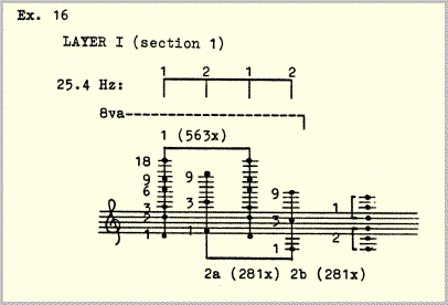
A typical layer I pattern. The speed is 25.4 pulses per second, divided among three different mixtures: 1, 2a, 2b. In this section there are 1125 layer I pulses; 1 occurs 563 times, 2a and b 281 times each. 1125 pulses at 25.4 pulses per second take 44.29" = duration of the section.
Thus the three layers represent different ways of subdividing the same hexachord, and of using the hexachord both as an harmonic source, that is, as a source of fundamental pitches, and as the source of the overtone structures of these pitches.

The derivation of harmonic movement from the interlocking change pattern illustrated in example 8 was accomplished by transposing the hexachord down a fifth or up a fourth in each section, in such a way that in 24 sections the circle of fifths is twice circumscribed, with half of the fifths (or fourths) in layer II changing from one section to the next while the other half remains constant. The root pitches of the hexachords are the products of these combinations and thus, analogous to levels 1, 3 and 5 of the time structure, change in each section.
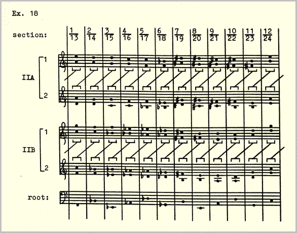
Layer II is the only layer which is melodically elaborated. The elaboration takes place in either A or B, alternating by sections. It consists of a single nine-pulse figure in 1 complemented by its inversion in 2. A figure of nine pulses was chosen because it can be combined with any of the melodically elaborated envelopes in layer II, all of which contain 9 or a multiple of 9,(27, 45) pulses (example 20). Ihe melodic motion, or the illusion thereof, is created by the crossing of the two versions of the figure through the same register on alternate pulses. The figure remains unvaried throughout the piece. It consists entirely of octave and fifth or fourth displacements of the intervals of 1 and 2. Ihe perceived variant forms of the figure are due to the changing velocity ratios between layers and to the changing pulse content of the envelopes. The constant crossfading of envelopes continuously shifts the accents of the combined 18-pulse figure from 1 to 2 so that no single dominating meter can emerge.
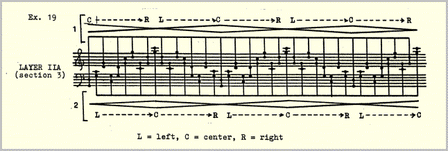
It remained to join this figuration to the harmonic scheme of example 18. This required two steps: first, I made a diagram of the sectional alternation of the figuration. Since the number of up and down motions in the figure is always odd it was sufficient for schematic purposes to draw three motions \/\ or /\/ to represent all of the sections. For comparison, the temporal scheme of example 8 is included in the lower half of example 20.
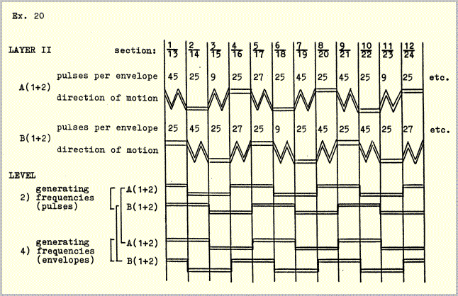
This diagram was then applied to the harmonic scheme of example 18 resulting in the following:
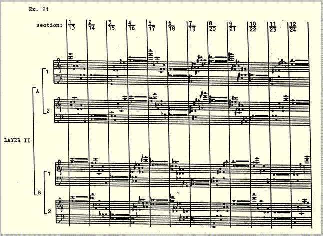
Here the three motions \/\ 1n example 20 have been further reduced to one; the upward form of a downward-directed motion is simply the same figure in retrograde and vice-versa. In A the rhythmic 1-2 alternation always begins on 1; in B it always begins on 2.
III
If two pulse series of different speed are allowed to partially fuse, a rhythmic figure - the result of the combination of the two series, will emerge.
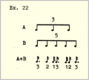
Resultant phenomena such as A+B, though most obviously rhythmic, have their harmonic, melodic and timbral equivalents as well. For this reason I sometimes prefer the more general (and less historically burdened4) term "second generation phenomena". Whatever you call them, they played an extremely important role in the composition and production of Pulse Music III because they constitute the aural background upon which the compositional program was worked out and because their effects were constantly taken into consideration in the many decisions of detail which were made in the studio. Ihe wish to set in motion more than one pulse velocity at a time brings with it the necessity of finding a balance between separation and integration of the individual pulse series, and the most effective means of gauging this balance is to listen for resultants. If the two pulse series A and B were to be completely fused, that is, identical in color, register, spatial location, attack, etc., then of course only the resultant would be heard. On the other hand, if they were completely unlike, then no resultant could emerge; there would simply be two discrete tickings.
Two sets of factors contribute to this balance. The first was built into the temporal and harmonic structures described above. It consists of
- similarity of timbre between layers.
- interlocking of layers by common pitches.
- fluctuation between separation and integration of pulse layers through continuous dynamic and spatial crossing. Integration is maximized where the pulse layers meet (halfway between the extremes of ff-center and pp-far left or right) and minimized where they are farthest apart. (I had learned from previous experiences that continuous fluctuation sounds much more "balanced" than literal stasis).
- the complementary relationship of the two generations. There is no internal rhythmic elaboration of the pulse series. Rhythmic events, the results of the crossing of pulse series, arise exclusively in the second generation.
The second set of contributing factors includes those elements of the composition which were adjusted during work in the studio. The way in which layers combine provided the criteria for these adjustments. For this reason it was necessary to produce a complete layer at a time, rather than a complete section at a time; the latter method would have made any consistency in the balancing of the layers practically impossible. The layers were recorded in the following order:
- trigger pulses
(highest frequencies, from which the other layers were derived subharmonically).
- layer II
- layer III
- layer I
- drone package
(a succession of 24 drone sounds derived from the pitch material of layers I, II and III).
- envelope coincidence markers
(framing each section).
The following kinds of adjustments were made during the recording of each layer:
- "registration", i.e. the registral location of the layers and of their component partials.
- microdynamics, i.e. the relative loudness of different partials within the mixtures. This is the single most important influence on color.
- attack and decay transients - including the many composite transients which resulted from pulse coincidences.
In similarly conceived instrumental music many of these kinds of adjustments would be left to the performer as choices of color, touch, articulation, etc.
It may be remembered that in both layers A and B the pulse series are always divided into two alternating halves, 1 and 2. Omitting the envelopes, even as simple an operation as this can lead to complex results by generating a polyphony of second generation rhythms as well as a concomitant polyphony of generations.
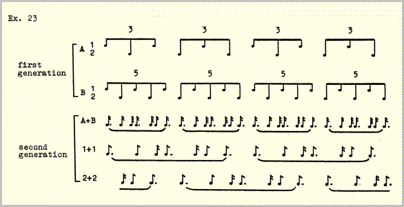
Resultant derivations like this encourage some speculative questioning. Do they need to stop at the second generation? Does this represent a logical limit, or could there be a third or even a fourth generation, eventually an entire array of generations or "alternative musics" taking place at once, so to speak at various angles to one another? Composition might be in this case less a matter of creating an object than of creating the conditions prerequisite to the emergence of alternative ways of hearing the same thing. Certainly the reciprocal derivation of generations (which one is the resultant of the other?) would suggest at least these and a few other lines along which future compositional activity could proceed, assuming of course that the composition of multiple and simultaneous aural perspectives - of a new kind of polyphony - would be of interest to the composer. But how could it not be?
Technical Notes
The Studio für Elektronische Musik at the West German Radio was not yet computerized in 1978. Its most recent acquisition was the EMS Synthi 100 synthesizer which generated all of the sounds used in Pulse Music III, two 8-ehannel Telefunken tape recorders, and the practically unlimited mixing facilities of a large radio station. There was also a great deal of older equipment left over from the "classical" era of electronic music, some of which had been gathering dust (or so it seemed) sinee the 1950s, lending the place an historic atmosphere not without charm - but that is another story.
To synchronize all the layers of Pulse Music III with the precision necessary to render the temporal relationships - above all the pulse coincidences - audible, a special circuit, called a trigger-pulse circuit, was developed. Example 24 is a simplified schematic drawing of this circuit.
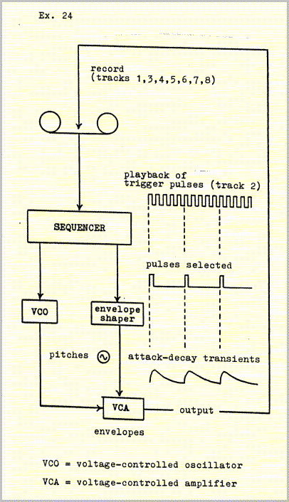
The circuit was used as follows:
- Trigger pulses were recorded on one track of an 8-track tape recorder. The frequency of the trigger pulses is different for each of the 24 sections. These frequencies correspond to level 1 of example 14.
- The trigger pulses were fed from the tape recorder into the "clock" sequencer of the synthesizer. The clock speed of the sequencer was thus controlled from the tape. The sequencer can be programmed to emit a signal on any selected trigger pulse or pulses. In addition to this purely temporal function of the sequencer, it ean also determine all of the voltages necessary for control of the voltage-controlled oscillators and amplifiers, that is, attack, decay, pitch and loudness. Further modifications were made with the usual analog equipment, filters, modulators, etc.
- The signals were recorded onto another track of the same tape on which the trigger pulses were stored. They are therefore exactly synchronous with the trigger pulses.
- The sequencer was reprogrammed to produce another pulse layer, which was recorded onto another track of the same tape. Since the pulse velocities in this layer are controlled by the same trigger pulses as the previously recorded layer, the two layers are synchronous. For example, if the sequencer has been programmed to emit a signal every three trigger pulses in one layer and every five pulses in another layer, the two repeating signals would coincide every fifteen trigger pulses.
This procedure was repeated until all the layers were recorded. In the ease of a tape recorder with eight channels this meant that several intermediate mixdowns had to be made because the seven tracks available for recording were not sufficient to complete all of the layers.
For this reason two 8-channel tape machines were indispensable. After completely filling 8 tracks on one machine, the recordings, including the trigger pulses, were transferred to the other machine and mixed down onto two or three tracks to make room for further recordings. This was done five times; a total of thirty tracks were needed to complete all the recordings. The final step was to splice together the twenty-four seetions, after which the trigger pulses were erased.
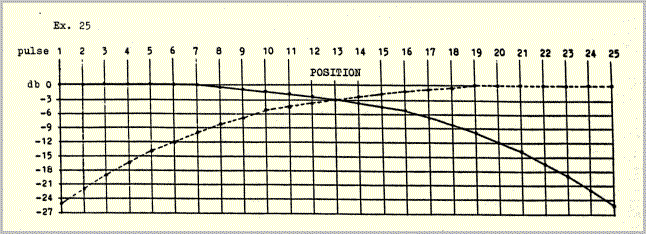
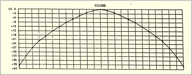
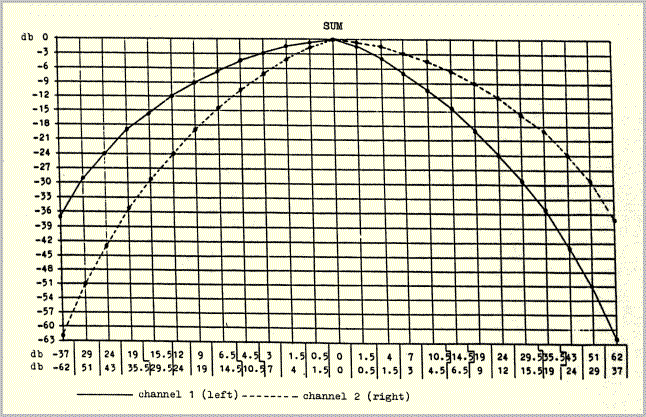
The spatial/dynamic envelopes are comprised of two types of volume curve - one to determine the positions of the pulses in space, the other to determine overall volume. The two types of curve correspond to the two complementary characteristics of the pulse movements: 1) each pulse series moves through space, either from left to right (layer II) or from front to rear (layers I and III). 2) These movements start very softly from an extreme position at the left or front, increase in volume as they approach the center, reach a peak exactly at the center point between two loudspeakers, and decrease again to very soft as they move on to the right or to the rear.
The first characteristic is produced by cross-fading two channels. Every pulse appears simultaneously on both channels; the relationship between the volume of the two channels determines the perceived spatial position with respect to the loudspeakers. With eight different pulse movements in play at all times (compare example 6) an extremely precise voltage-controlled crossfading program was needed to keep the texture clear. The position of each pulse was regulated individually according to two volume curves, as shown in example 25, "position": the pulses move from left to right.
The overall volume of the moving pulses was regulated by a superposed volume curve, again programmed with a different voltage for each individual pulse (example 25, "volume"). The sum of the two types of curve yielded the desired waxing- waning movement in space (example 25, "sum").
In the first experiments the programs for position and overall volume were run separately, in two consecutive steps. After the accumulation of some experience it was possible to program the sum-curves directly in a single step. (Though the volume curves in example 25 may look "mathematical", they are really the products of experiment and comparison). Seven such curves were worked out: four (for envelopes eontaining 9, 25, 27 and 45 pulses) for layer II, and three (for envelopes containing 15, 45 and 75 pulses) for layers I and III. The curves function of course independently of pulse velocities. Example 25 illustrates the curves used for envelopes containing 25 pulses; it would correspond, for example, to the lower envelope (2a,b) in example 1. The upper envelope in example 1 would start in the middle of example 25 at the thirteenth pulse.
References
1 Pulse Music III was produced between July 1978 and January 1979. The first performance took place in the Roman-German Museum, Cologne, on January 15, 1979, as part of the West German Radio's "Musik der Zeit" concert series. Technical collaborators in the production were Volker Muller and James Whitman.
2 Beyond this no attempt was made at a naturalistic depiction of continuous changes of distance. Additional contributing factors such as alterations of pitch (doppler effects), tone color and reverberation would have resulted in the erasure of distinctions between what were intended to be independently perceptible pulse layers.
3 Karlheinz Stockhausen, '...how time passes...', in Die Reihe, vol. 3, Theodore Presser, Bryn Mawr, 1959.
4 I take the term "resultant" from Joseph Schillinger, who based an elaborate system of composition on rhythmic resultants like the one in example 22 (Joseph Schillinger, The Schillinger System of Musical Composition, New York, Da Capo Press reprint series, 1978). An illuminating investigation of resultants is to be found in: Maury Yeston, The Stratification of Musical Rhythm, New Haven and London, Yale University Press, 1976.
